Weekend Project: The Message Box
Having a small character LCD hooked up to a computer isn’t really a novel idea. They became popular on servers, which often run without monitors attached, to convey vital system status information to technicians. In more recent years, they have become popular in custom-built PCs. I wanted one on my desk because there are often small notifications that I want to be accessible at all times, but not the center of my attention. On-screen notifications, such as icons in the GNOME panel, the Windows system tray, or Growl on Mac OS X work fairly well, but only if I’m sitting at my computer and have the monitors turned on. An external notification device is able to convey this information without a large display.
I could have purchased a pre-built unit; they exist both as displays that fit into an empty expansion bay on the front of a PC, or separate desktop units. However, my aesthetics don’t always match up with the PC-modding community (I tend to prefer things simple and understated rather than bright and flashy; I don’t want my PC to look like the typical “gaming rig”).
Building things yourself is great because you get to decide exactly how it’s going to look and work. I also chose to add 3 RGB LEDs to the device—many small bits of information are binary, such as having a new e-mail message. The LEDs provide a great way to convey information like this, and they’re meaningful from across the room. Using RGB LEDs makes them customizable, or allows information to be encoded in the color of the indicators.

Specifications
- Enclosure: Recycled Apple power adapter packaging
- LCD: 2 line by 16 character display, using the ubiquitous HD44780 controller
- Microcontroller: ATmega168, using the internal RC oscillator
- Interface: USB, using the FT232R chip for USB-to-serial
- LEDs: 3 RGB T1-3/4 LEDs
Construction
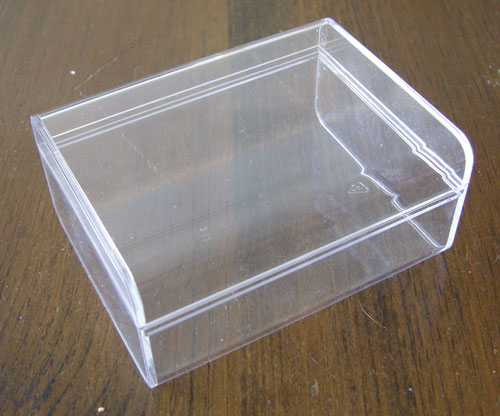
Rather than designing a custom PCB and fabricating a custom enclosure, I decided that I’d put together the Message Box as a true weekend project, using only materials I had around in the parts bin. The enclosure that I chose is the plastic box that Apple uses to package their chargers for the iPhone/iPod touch. It was perfect for re-use in a project like this.
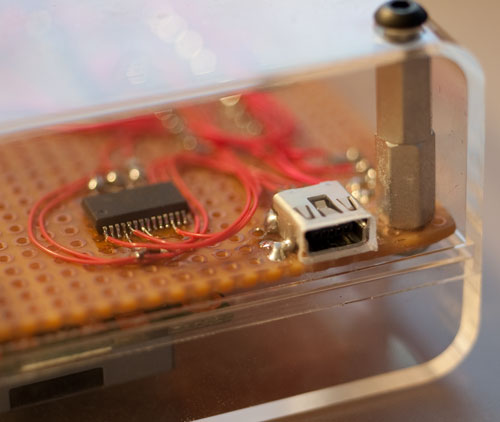
I started by cutting a piece of perfboard to fit the inside of the box. I drilled four holes in the corners of the board and the box so that the board could be mounted on standoffs. I soldered a USB mini-B jack to the edge of the board, then drilled and filed out an opening for it in the plastic.
After confirming the fit of the board in the box, I placed all of the large components on the board: the LCD, the ATmega168, and the 3 LEDs. I checked the fit in the box and then soldered them down.
The FTDI chip that I used to provide the USB interface is only available in surface-mount form. There’s a nice evaluation board with the chip and a USB port on it that I’ve used before in other projects, but I didn’t have any sitting around. The prefabricated evaluation board also adds about $20 to a project, where the chip itself and a USB connector can be sourced for a couple of bucks.
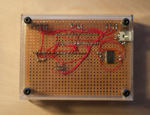
To use the surface mount chip, I placed a piece of Kapton tape on the bottom of the perfboard to keep the pads from shorting out the pins on the chip, and epoxied the chip to the tape. The whole board is wired point-to-point using 30-gauge wire. Soldering the wire directly to the pins of the chip takes a reasonably fine iron tip and a little bit of practice, but it’s really not bad once you get the hang of it.
I then proceeded to wire up the rest of the board. For the passive components, I used 0603-size surface mount resistors and capacitors. These are actually great for point-to-point work like this, because they fit perfectly between pins with the standard 100-mil through-hole spacing. The bypass capacitors fit neatly between the power and ground pins on the chips, and the LED resistors take up hardly any space at all. You just need a good pair of tweezers for placing them accurately.
Firmware and Software
I wrote the firmware for the device in C, using the avr-gcc toolchain. There is a 6-pin ISP socket on the back of the board to enable the microcontroller to be programmed.
The device appears under Linux as a standard USB serial port (/dev/ttyUSB0). I
set up the protocol so that any text written to the port appears on the
display. I also implemented a very limited subset of the VT100 terminal command
set for operations such as clearing the display and positioning the cursor. To
control the LEDs, I added a few custom escape sequences.
On the PC end, I wrote a Python script that updates the information on the display. It periodically polls a variety of sources such as RSS feeds, e-mail inbox message counts, instant message clients, and music players, and then updates the text on the LCD and the state of the LEDs accordingly.
Conclusion
The Message Box is a great little device; I’m glad I spent the time building it. I’m still tweaking the code to make it do different things and customize the functionality, but that’s what’s great about having a custom-built solution—in the end, it will do exactly what I want it to do.