Lenovo Bluetooth keyboard repairs
For one of my home desktop setups, I have very particular keyboard requirements. Since I put the keyboard in my lap (there’s no desk/table, the monitor is suspended on a cantilevered arm) the pointing device needs to be integrated into the keyboard itself. I’ve become less of a fan of trackpads over the years, especially the terrible ones that are integrated into cheap wireless keyboard combos like the ubiquitous Logitech K400. Furthermore, as it’s a Linux machine and I’m very accustomed to the X11 clipboard, which uses the middle mouse button to paste, I want a physical middle button. I’ve only found one wireless keyboard that meets those requirements, and it’s Lenovo’s bluetooth keyboard with a TrackPoint:
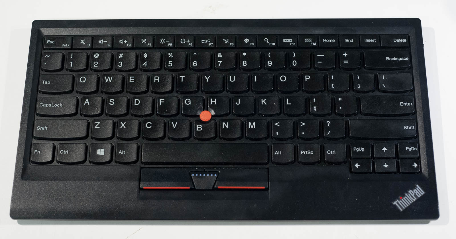
I like the keyboards and TrackPoints on my ThinkPads, so it’s nice to have the same setup. Unfortunately, the wireless keyboard is a bit of a regression from the ones on my ThinkPads: it lacks the row above the function keys, the function keys have tiny markings with big icons for their secondary functions (which I don’t care about) and the build quality is overall not as good as older ThinkPads. I also don’t like Bluetooth (pairing is complicated, and it doesn’t work in the bootloader/BIOS). But, it works. Well, it did, at least until my TrackPoint stopped working one day. The keyboard continued to work, but the TrackPoint started drifting incessantly to the upper left no matter how it was deflected, followed by ceasing to work altogether (including the buttons) a couple of days later.
Searching for others with the same issue led me to this surprisingly recent and relevant GitHub issue. I suspected it might be an issue with the keyboard’s firmware, that it had gotten into some state where it had disabled the TrackPoint (most ThinkPads with the Windows drivers had a hotkey to disable the TrackPoint; did the wireless keyboard perhaps have a similar, but undocumented function?) Attempts to reset the keyboard (disconnecting the battery, holding different keys on powerup) didn’t bring it back, though. I did discover a few things that would cause it to lose its Bluetooth pairing, suggesting a reset of some sort (holding the Esc key when connecting the battery seems to do this), the TrackPoint still didn’t come back.
Removing the circuit board and inspecting the traces on both sides led to more insight about how the keyboard works. In all ThinkPads I’ve seen (up through my T420s, at least) the TrackPoint controller is on a small PCB physically attached to the TrackPoint itself on the back of the keyboard. The TrackPoint is a couple of strain gages; the controller reads the strain gages, does some dynamic calibration, and translates the result into cursor movement, which is communicated to the computer over PS/2. The wireless keyboard is missing the controller on the TrackPoint itself. Instead, a 4-conductor flex cable goes back to the main board.
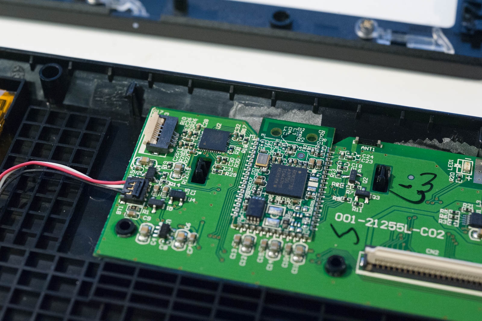
The main board has two microcontrollers on it. Most of the functionality appears to be handled by a BCM20730 SoC, which is intended for implementing Bluetooth HID devices. This chip sits on a module mounted to the mainboard with castellated vias along the edge. It has a built-in trace antenna, though for whatever reason the keyboard designers have chosen to use an external antenna on the mainboard instead. The UART pins on the module are wired to test points on the bottom of the board with their functions labeled; these points are accessible without disassembling the keyboard by removing the label from the bottom. This is probably how the keyboard’s firmware is initially programmed.
The signals from the keyboard matrix connector all route to this module, with the exception of the mouse buttons, so the module seems to be handling the keyboard functionality directly. The second chip, on the mainboard itself, appears to connect to the module through I²C (judging by the labels on the test points on the bottom of the board) though I didn’t actually probe the signals to confirm this. This IC, which is labeled 502A6 HF372 7AV1 in my unit, isn’t something I’ve been able to identify. I suspect it might be an ASIC based on the lack of any programming interface. Otherwise, it would have to be preprogrammed before being installed on the board.
This second IC appears to be the TrackPoint controller, and on my keyboard appeared to be poorly soldered. I was unable to visually confirm good connections between most of the pads. Removing the chip with hot air didn’t change my keyboard’s behavior—the keyboard continued to pair and work perfectly, while the TrackPoint was dead. This confirmed that this IC is not used for the keyboard functionality and must just be the TrackPoint controller.
Inspecting the bottom side of the chip under a microscope (I unfortunately did not take pictures) made me extremely doubtful that some of the pads had ever had solder on them; they appeared dull and oxidized. I cleaned off the PCB and the chip with solder wick, and re-soldered the chip using leaded solder. When I connected everything again, I once again had a working TrackPoint. I can’t say I’m impressed with the quality control for an $80 keyboard.
Repair Guide
To help others who are having the same or similar problems, I’ve put together some instructions for performing the fix. This isn’t really an exhaustive guide and requires some expertise, but hopefully will be useful to someone.
There are only three screws in the entire assembly, and they hold the TrackPoint on to the bottom of the keyboard. Everything else is just press-fit or stuck together. The top frame just pops off. I started in the bottom left corner, and didn’t need any tools other than my figners to start removing it. (If yours is tight, a plastic spudger might help).

Continue to work around the outside until the frame is freed from the bottom all the way around.
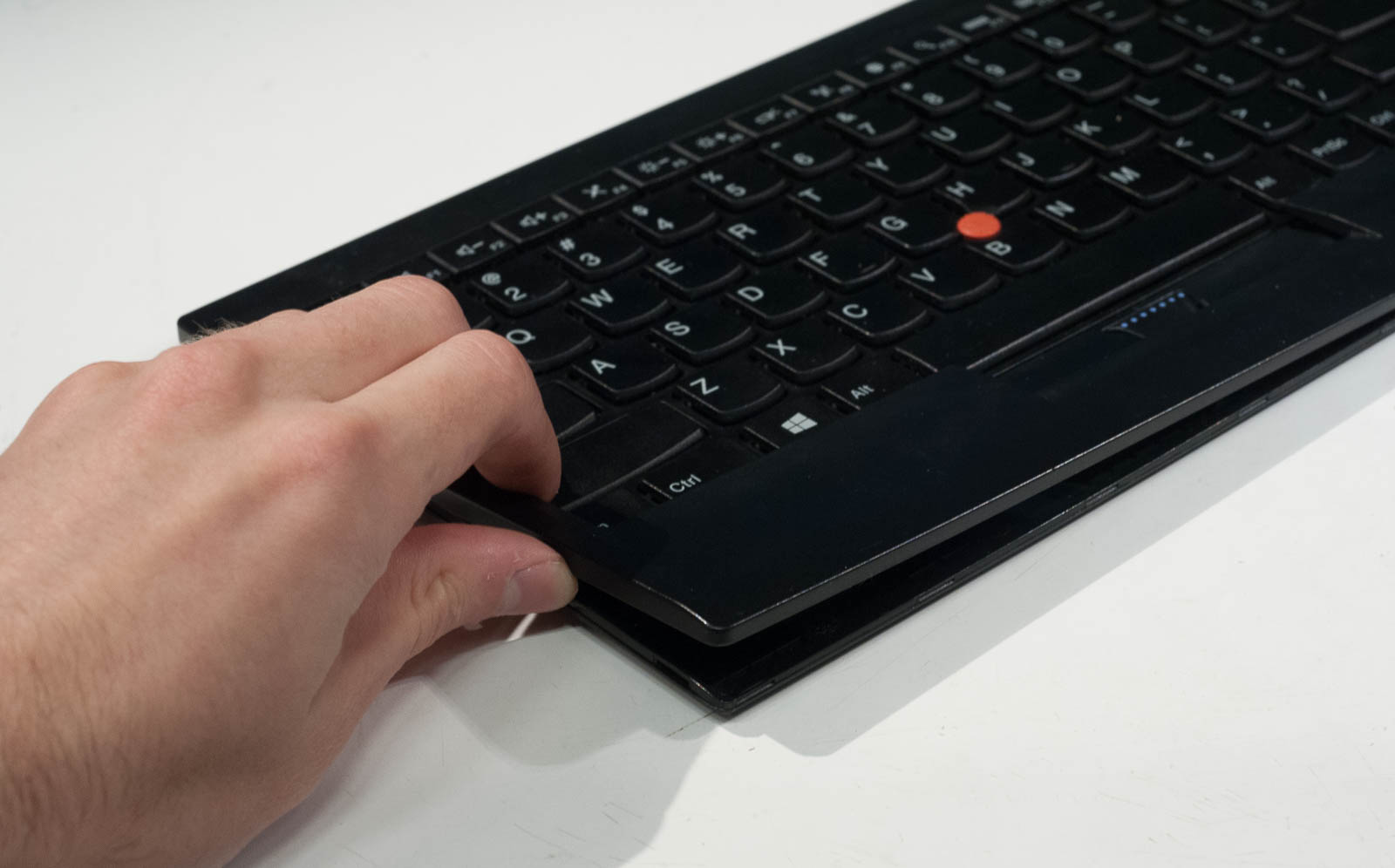
Once the frame is off, peel the keyboard up from the base. It’s just stuck down using double-sided tape. Make sure to pry underneath the metal backing and not the plastic bezel. Be aware that there are two cables attached to the bottom of the keyboard: one for the keys and buttons, and another for the TrackPoint. The keyboard cable is fairly large and robust and has some extra length, but the TrackPoint cable is thin and fragile. I suggest releasing this from its connector as soon as you can to reduce the risk of damaging it:
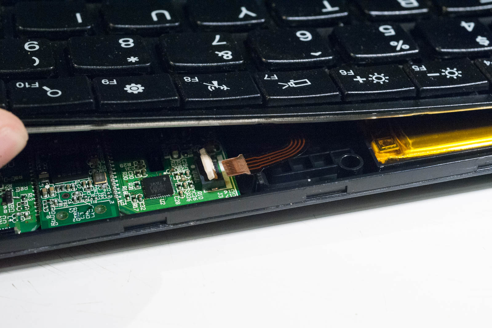
The adhesive can be reluctant to let go, but just be patient and apply gentle, continuous force as it comes free. Just be careful not to tear the cables or bend the keyboard.
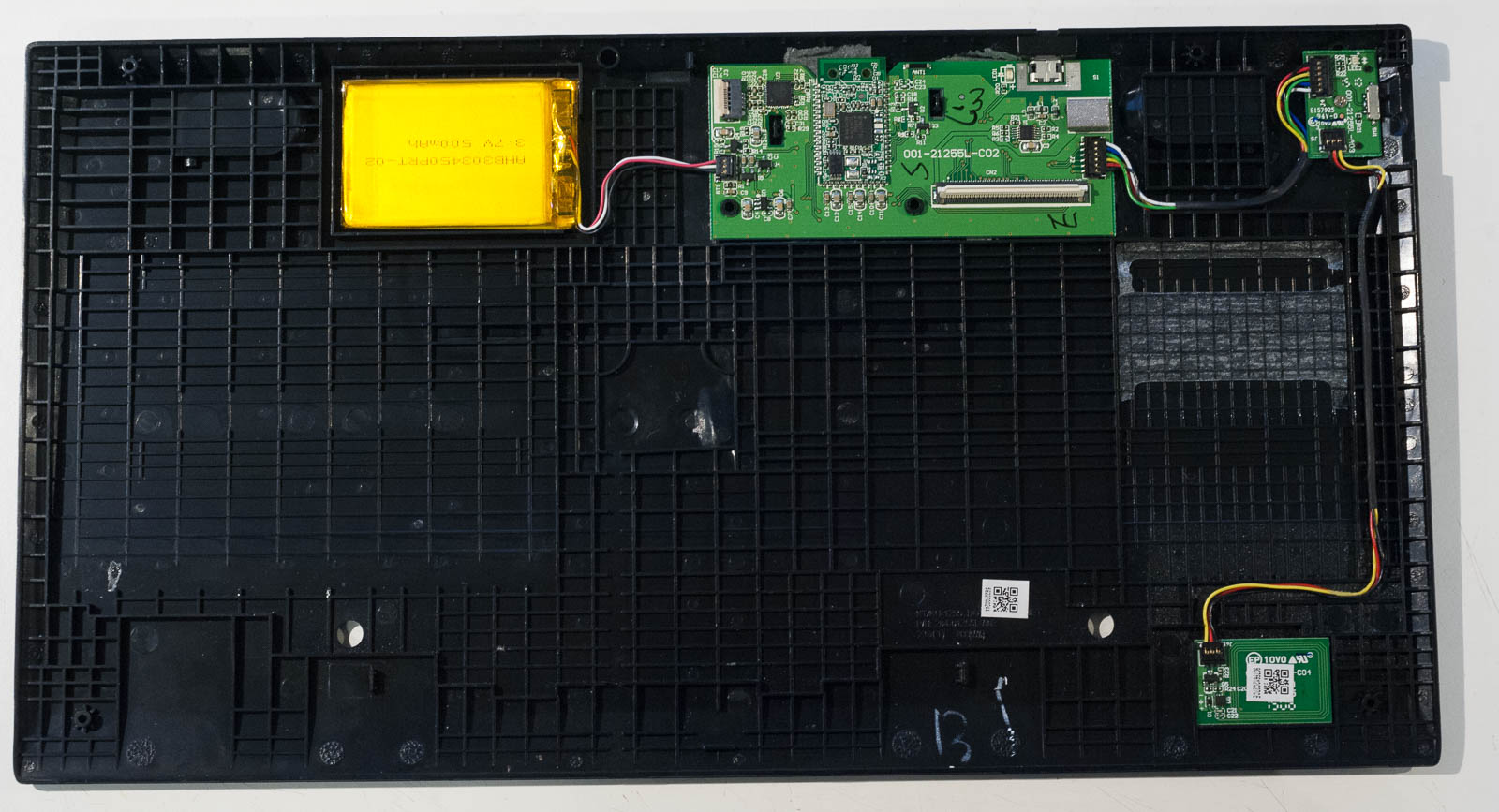
With the keyboard disconnected and removed, this is what’s left inside the case. There’s the battery, the main board, a small PCB with the LED and switch, and the NFC pairing board along the front edge. Make sure to disconnect the battery connector before doing any work on the PCB so you don’t short anything.
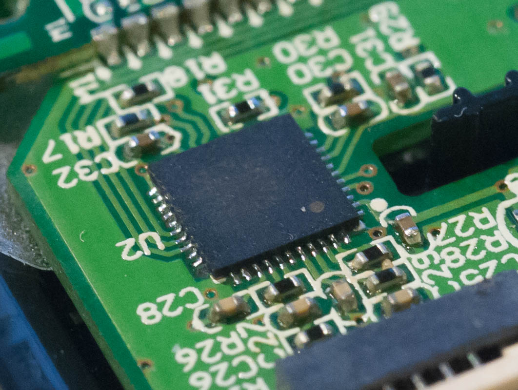
The chip we’re interested in is U2, at the upper left corner of the main board right next to the TrackPoint connector. At this point, there are two options. The first is to remove the chip with hot air, clean the chip and PCB, apply the proper amount of solder paste, and reflow. However, if you don’t have all of the equipment for that, repairs might be possible with an iron with a relatively fine tip and a good flux. Apply the flux (I recommend this stuff, it is expensive but fantastic) so that it coats both the pads on the board and the side of the chip. Put a small blob of solder on your iron tip, and run it along the side of the chip. The idea is that you want the blob to touch both the pads and the side of the chip, but the tip itself shouldn’t physically drag across either (the pads on the board are very easily scraped off, especially several without traces connected to them). If you’re doing this correctly, the perfect amount of solder should be left on the pad and the chip without leaving bridges between adjacent pads. If you do end up with bridges, add more flux and try again. Note that the tip doesn’t need to be particularly fine, as long as it’s not so big that you can’t avoid the passive components nearby.
Given my initial assessment of the board, I am doubtful that simply heating the chip without additional flux and solder would fix the problem (lead-free solder really does not flow nicely). However, if you have a hot air gun it might be worth trying before attempting the above. I would still add some flux, and possibly apply some gentle pressure to the top of the chip while heating, though be careful not to slide it around on the board.
A properly soldered chip should look something like this:
Note how you can see nice fillets that go between the pad on the board and the exposed copper on the side of the chip. There might be connections underneath even if you can’t see these fillets on the side of the chip, but seeing them gives you a nice confirmation that you have a good mechanical and electrical connection.
If things are working again, the reassembly procedure is basically the reverse of disassembly. Make sure that the cables that go between the boards are routed through their proper channels, reconnect the keyboard matrix and trackpoint cables, and stick the keyboard back down (there are a few features in the plastic that help you align it). Stick it down lightly and then apply pressure from the middle outward—this will help ensure that it stays centered and even.
I’d be interested in hearing if this helped fix your broken TrackPoint, or if you have any suggestions to improve this article.