Robot Finger E-Field Sensor Board
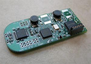
This board that I developed fits inside of each of the three fingers of Intel Labs Seattle’s mobile robot. It includes two resonant transmitters for generating high voltage AC signals, two analog front-ends for amplifying the received current to be fed into the microcontroller’s ADC, and enough processing in the microcontroller to perform synchronous demodulation on the received signal.

Each transmit-receive pair has unique geometry and constitutes a unique measurement. Within a single finger, four different transmit/receive channel pairs are possible: with the current antenna configuration in the fingers, there are split left and right receive electrodes and mid- and short-range transmit electrodes. Each finger can also be linked to a third transmit electrode in the palm of the hand, which provides additional left and right long-range channels.
Specifications
- Microcontroller: 8-bit AVR at 20 MHz
- Interfaces: USB via FTDI chip, I2C and analog outputs to palm board
- Transmit channels: 2 tunable transmitters
- Receive channels: 2 amplified receivers
- Transmit frequency: 156 kHz
Design and Construction
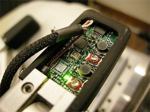
The board is designed to fit entirely within the fingertip links of the BarrettHand Grasper, a standard robotic hand widely used in research. The stock aluminum fingertips are replaced with plastic 3-D printed parts that are mostly transparent to electric fields. To fit all of the electronics into the fingers, I used QFN ICs and 0402 surface-mount components. The sensor boards are stacked on top of a transmit electrode board and a perpendicular receive electrode board inside the plastic fingertips.

An on-board USB-to-serial chip provides a way to interface an individual finger directly to a PC for development and debugging. When installed in the hand, the finger boards communicate via an I2C interface to another board in the palm of the hand, which aggregates the measurements from all of the fingers and sends them back to the PC over USB.