Milling Circuit Boards
For the past 12 or so years, the AT86RF23x 802.15.4 radios have been my go-to for low-power digital communication. They work pretty well, and I have a good software stack and protocols built up around them (which my friends decided should be called “Bri-Fi.”)
They’re sort of expensive, though—the bare chips are a few dollars each and modules were at least $20-30 last I looked. On a fully custom sensor board they’re not that bad, but for random side projects where I just want two things to talk to each other wirelessly, the cost of the chips and doing an RF layout are kind of annoying.
I’ve been seeing a lot of Nordic’s nRF24L01+ radios in the maker community. It seems there’s a pretty good Arduino library and the modules are available super cheap. I think I got five complete modules for about what I’d pay for one of the RF233 chips.
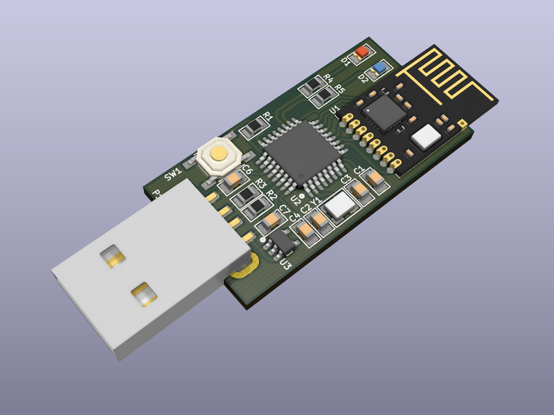
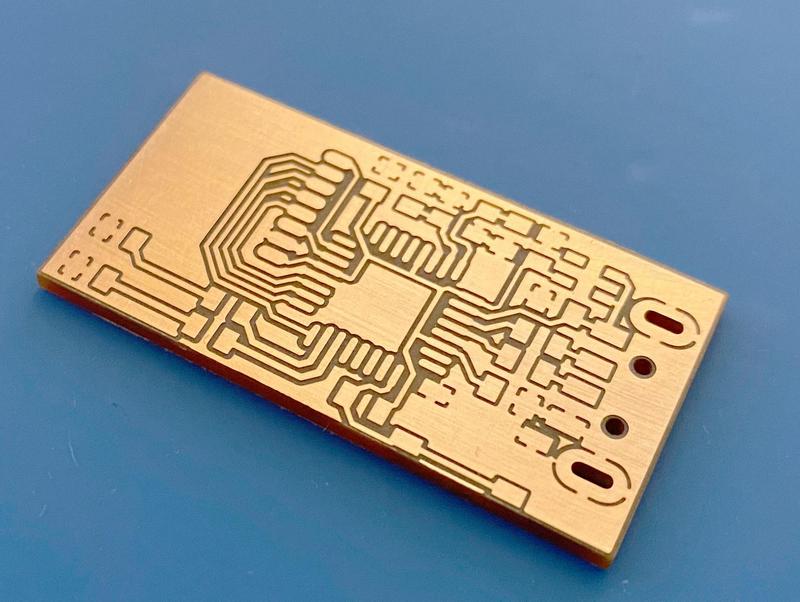
Anyway, I’m playing around with these modules and put together a couple of quick PCBs to try them out. I’ve been getting pretty good results milling boards at home using my little CNC router, so I thought I’d snap a few photos and write a “quick” blog post. This board is a little USB-to-RF bridge based around the ATmega32U2. If this works, it’s going to be the computer side of a custom user input device.

I’ve also been working on switching from Altium to KiCad (which in addition to being free runs without needing a virtual machine on my Linux desktop) so simple boards like this are a good way to get used to the new workflow.
For many years, I used the “fab modules” from the How to Make (almost) Anything class to convert my layouts to G-code for milling. I had a script that would take a PDF exported from Altium, separate out the layers, rasterize them, and pipe them through the command-line fab modules to produce a set of toolpaths. But the fab modules have changed a lot since then (they’re now primarily browser-based, which is great if you want a GUI but makes automation a bit trickier) and the Altium PDF export thing was always a hack.
Since I’m switching to new layout software on a new computer (which doesn’t have my ancient copy of the fab modules) and a new CNC router, I decided to try something new. I’ve been using a program called pcb2gcode, which has been working very well. It takes gerber files exported from KiCad and generates toolpaths. The whole process is quite seamless.
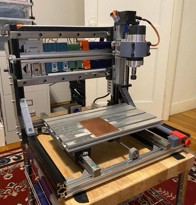
The CNC router is probably a subject for a whole series of posts that I may or may not ever get around to writing. It started as a pile of parts from one of the ubiquitous cheap “3018” CNC kits which are quite lousy as sold. In the process of trying to improve it, I basically ended up building an entirely new machine.
Another deviation from the fab class process is the tooling. The class uses 1/64″ endmills from Carbide Depot, which are about $17 each. I’d generally get about 10 small boards out of a well-cared-for one before it started getting dull, which isn’t a terrible cost-per-board, but they’re also so small that they have a tendency to break if even slightly mistreated. They’re also a bit on the big side for some components—1/64″ is about 16 mils or 0.4mm. That just barely works for TSSOP ICs with 0.65mm pin spacing if one makes the pads so narrow that they’re no wider than the traces. For the class it’s not a huge issue since people tend to work with 1206 passives and SOICs or 0.8mm QFPs, but it certainly limits density and makes it harder to work with some more interesting parts. 0.01″ endmills can also be used, but these break if you look at them funny.
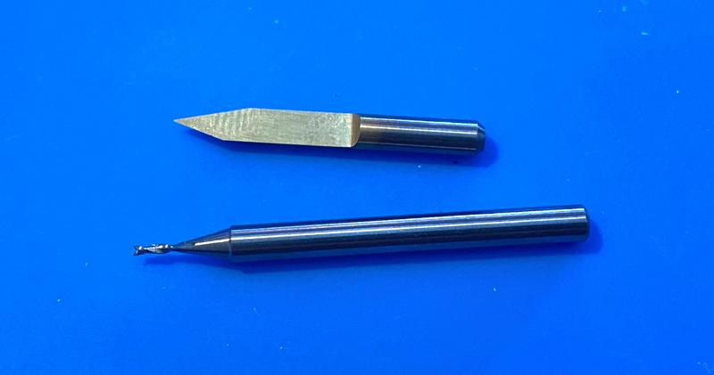
Instead, I’ve switched to using a 30° v-bit engraving tool to mill in between the traces. These are basically a single-flute D-bit cutter. Half of the shank is removed (leaving a D-shape) and sharpened to a point. It’s relieved on one edge so there’s only one cutting surface. The benefit is that there’s the maximum possible amount of material supporting the cutting edge, so it’s a lot less fragile than a complex multi-flute endmill geometry while still coming to a very sharp point. This means, though, that the width of the cut is dependent on the depth of the cut—the board either needs to be perfectly flat in the machine, or you at least need to compensate for variations in height in the toolpath. I solved this problem with auto-leveling. I connect wires to the blank PCB and the tool with alligator clips, and then the machine probes downward until the tool touches the board, completing a circuit. By repeating this process on a grid over the surface of the board, the machine can automatically map out the height of the board and compensate in the toolpath.
In my current configuration I’m milling at a depth of 45μm, which is giving me a cut about 140μm (about 6 mils). In theory that should be good enough to make footprints for 0.5mm QFN parts, but I haven’t tried pushing the process that far yet.
I haven’t milled enough boards to determine how long these tools last yet (though I’ve dulled a couple by crashing them into the board when adjusting the Z-height). I think I’m on the fourth board for my current tool and it’s still cutting nice and sharp. And they’re only $14 for a pack of ten, so they are significantly more economical than the 1/64″ endmills.
To drill any holes and cut out the finished board, I’m using an 0.8mm 2-flute endmill, which is the same as the fab class process. These cheap ones I’m using don’t last for very long before they get dull and leave a bit of a burr on the edge, but they work.
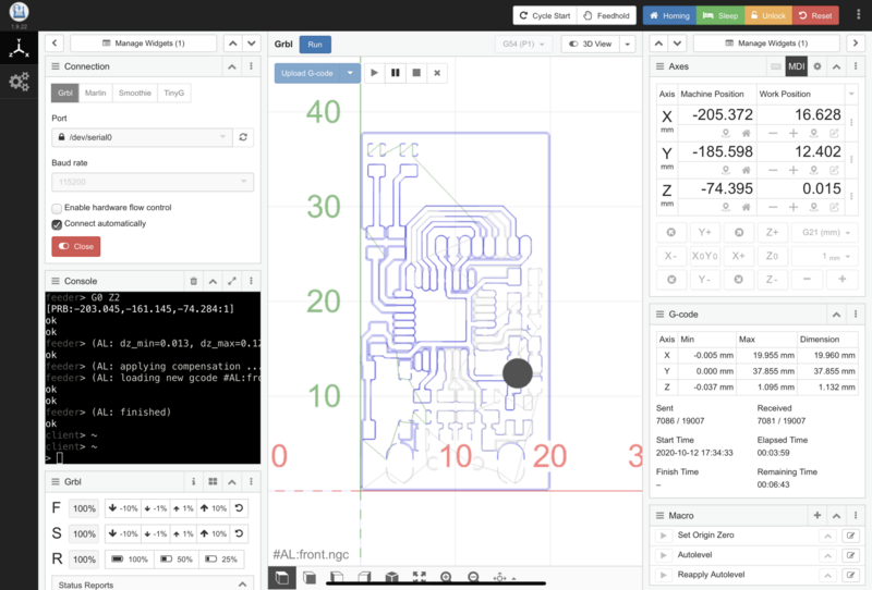
The control board in the router is the original from the 3018 kit, and it runs GRBL, which is a pretty basic CNC controller designed to run on Arduino-based hardware. It’s not fancy but it gets the job done. As an interface, I’m using the excellent cncjs, which I have running on the Raspberry Pi clipped to the back of the machine. This combo is pretty great—I just plug the machine in, it connects to my Wi-Fi, and I can open up a web browser to upload a G-code file and control the machine. I’m using this extension for cncjs which implements the autoleveling. After uploading the G-code for the board, I run a macro that invokes the extension, which probes on a grid and then modifies the G-code in place to account for any variations in board height.
In the end, I’m quite pleased with the results. It’s taken a lot of tuning to get everything dialed in, not to mention the long process of building the machine, chasing rigidity and reducing backlash… but it now seems to be working pretty well. This board took about 10 minutes to mill the traces and another 5 or so to cut the holes and the board outline. This definitely isn’t a process I’d use for really complex boards or anything I need multiple copies of, especially when PCB fabrication services are so readily available and cheap now, but sometimes it’s nice to be able to go from an idea to a completed board within a single afternoon.
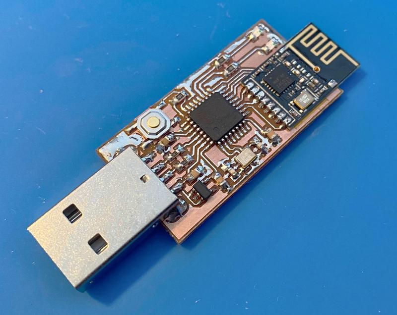
Now I just need to write some code to see how well I like these radio modules for my application.