Project Preview: LED Matrix Display
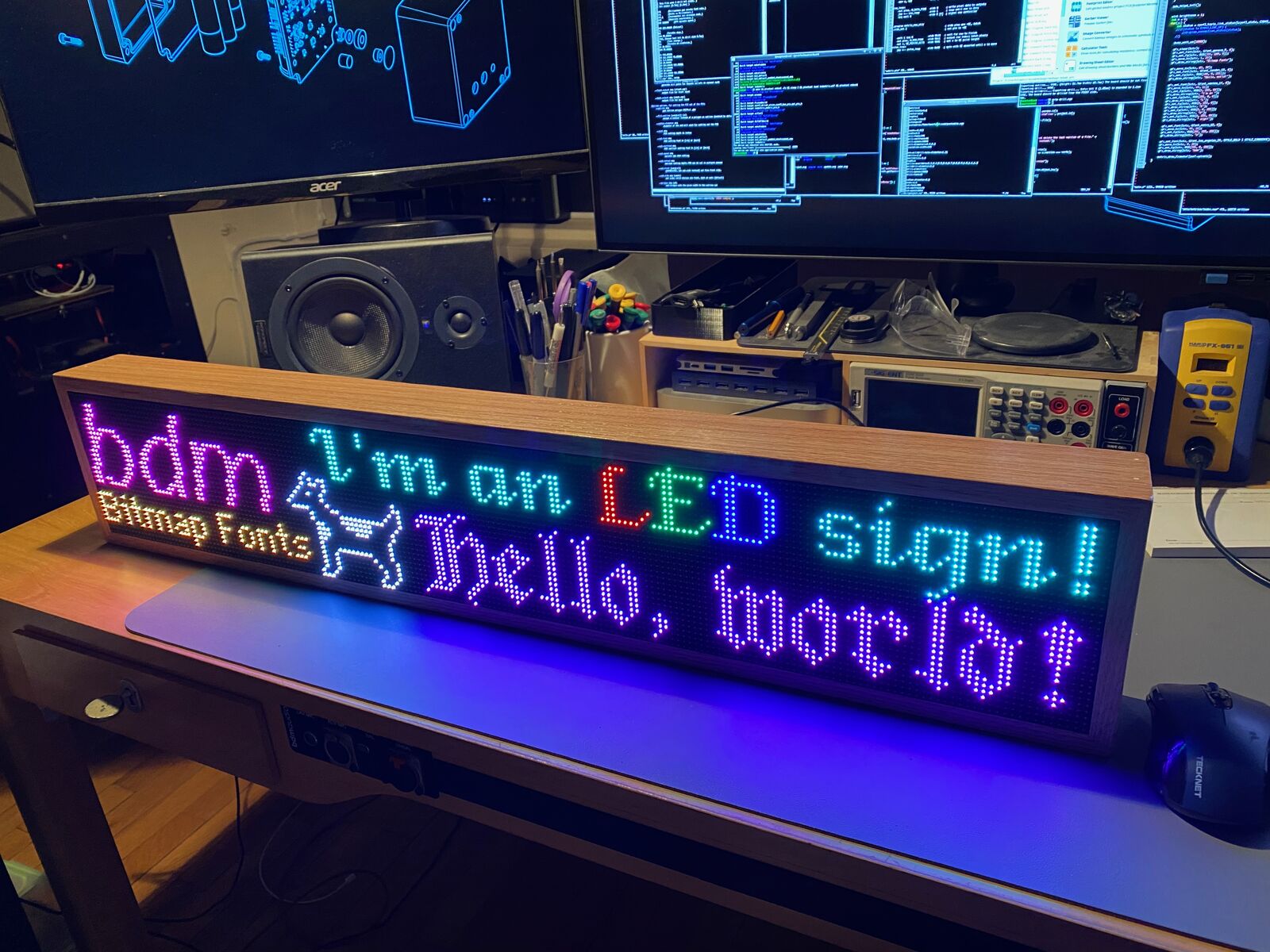
This is still a work in progress: a full series of articles should be on the way, but I wanted to give a quick preview of a project I’ve been doing to explore the PIOs and network functionality of the RP2040/Raspberry Pi Pico W.
This series will feature a little bit of everything:
- The RP2040’s PIOs
- Wi-fi and networking with LwIP
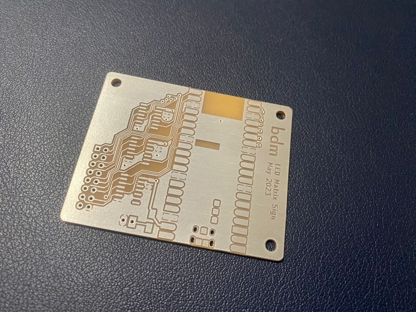
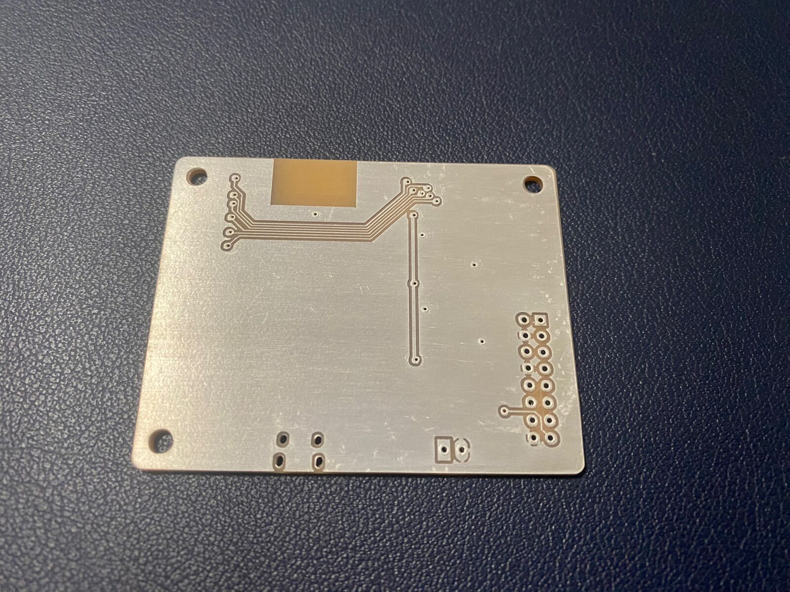
- 2-layer PCB milling and fabrication, with vias
- Woodworking
- 12-bit color graphics
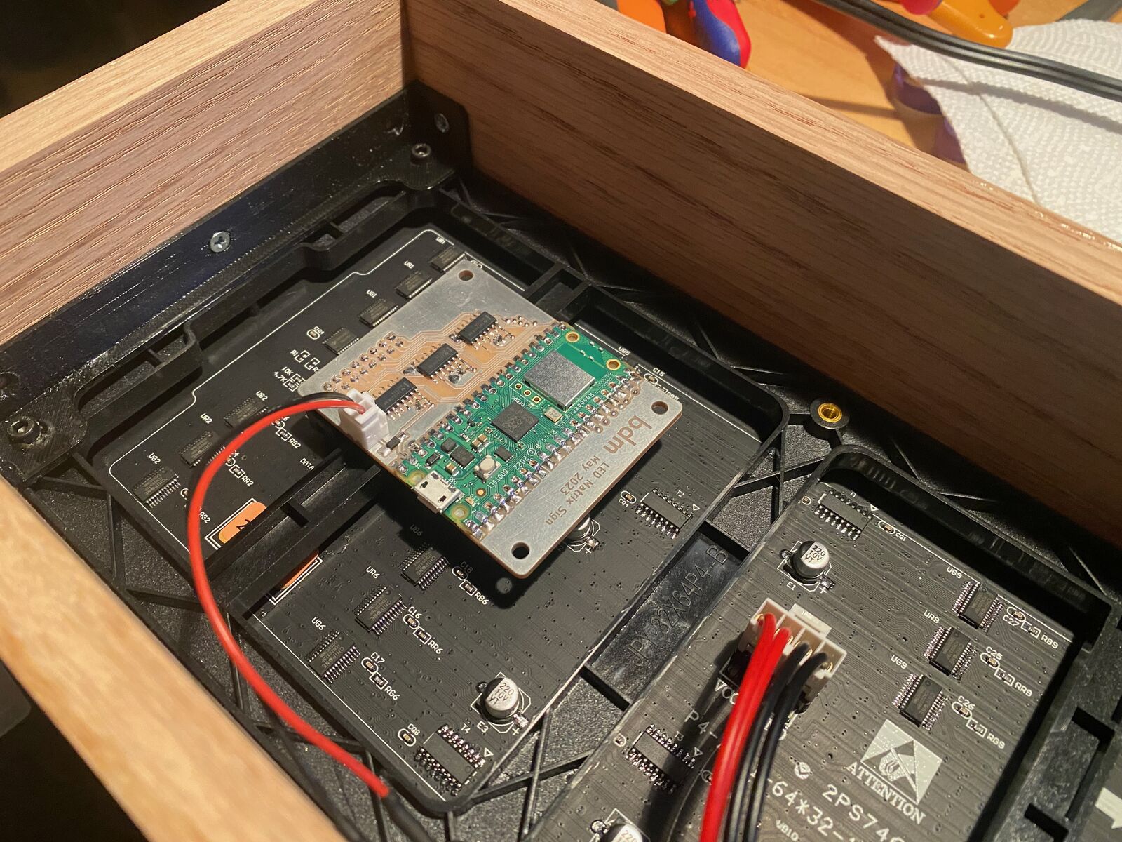
- LED matrix modules and high speed shift registers
- 40-year-old classic Macintosh typography
So, hopefully more content coming soon. In the meantime, here are a few more photos:
And here’s a peek at the PIO code. This goes along with a fair bit of setup in the C code to configure everything and feed the framebuffer to the FIFOs using DMA, but the PIO programs themselves are nice and small.
.define PUBLIC N_DATA_PINS          6
.define PUBLIC N_ROW_PINS           4
.define PUBLIC OE_PERIOD_BITS       8

.program matrix_pixel_ctlr
.side_set 1                             ; side pin is pixel clock
                                        ; out pins are pixel data

    mov x, isr              side 0      ; copy row width into x

row_loop:
    out pins, N_DATA_PINS   side 0      ; write pixel data to outputs
    jmp x-- row_loop        side 1      ; loop until row is done
    irq wait 0              side 0 [4]  ; signal row controller


.program matrix_row_ctlr
.side_set 2                             ; side pins are ~OE, latch
                                        ; out pins are row select lines

    wait 1 irq 0            side 0b10   ; wait for row to finish
    out pins, N_ROW_PINS    side 0b11   ; output row index; latch pixels
    out x, OE_PERIOD_BITS   side 0b01   ; set x to OE pulse length
pulse_loop:
    jmp x-- pulse_loop      side 0b00   ; spin with OE asserted until x is zero